Die
Deprocessing
Die
delayering or
deprocessing is the
semiconductor failure analysis technique of
stripping off
the upper layers of the die to
expose a defect site that
is buried underneath these layers.
Die delayering is usually done as a
sequence
of steps, removing a
layer or two at a time. Since
each layer is chemically and physically different from the others, the
delayering steps are different from each other as well.
Many
die delayering techniques exist, e.g., plasma etching, reactive ion
etching, wet chemical etching, etc.
A typical die delayering sequence starts with either plasma or
reactive ion etching to remove the nitride passivation on top of the die
surface, followed by a series of wet chemical etching steps to remove
the rest of the die layers.
Plasma etching
is a dry and
anisotropic (in one direction only) etching
process that consists of the following steps: 1) a glow discharge
produces
chemically reactive
species from a relatively inert gas; 2) the species diffuse to and get
adsorbed by
the surface to be etched; 3) the species
reacts with the surface, producing a
volatile byproduct; 4) the byproduct is
desorbed from the surface, completing the
etch process; and 5) the byproduct is
released to the bulk gas.
Reactive ion etching is
similar to plasma etching, except that it involves
bombardment of the
surface being etched with accelerated
reactive ions. These accelerated ions
sputter
material off the substrate as they hit its surface, as well as
react
with the substrate
material. Thus, with RIE, etching is accomplished by two
processes:
sputtering and
chemical reaction.
Wet etching
involves the application of
liquid
solutions
to the die
surface to remove one or more layers of materials or to highlight
defects. The chemicals used during wet etching depends on the etching
selectivity
desired. For example, HF is
not selective, i.e., it can be used to etch out almost all the layers on
the die surface. On the
other hand, hydrogen peroxide is highly selective and would etch out
only the TiW layer on the die surface.
Wet etching is always followed by a an acetone or alcohol rinse,
which in turn is followed by a D.I. water rinse.
 |
|
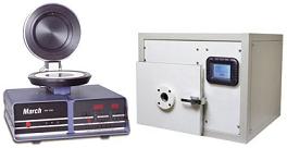
Figure 1.
Examples of Reactive Ion/Plasma Etchers |
Table 1
shows examples of die deprocessing steps. Note that the amounts of
etch time were not included in this table because these will depend on
the thickness of the layer to be etched.
Silicon
defects may be
highlighted
with either a
Wright etch or a SIRTL
etch.
Table 1.
Examples of Die Deprocessing Steps
|
Layer to
be Etched |
Example
of Useable Etch |
|
Nitride
Passivation |
RIE
using 90%/10% CF4/O2 gas mixture |
|
Silicon
Dioxide |
Silox
Etch at 25 deg C |
|
Aluminum
Metal Line |
Phosphoric/Acetic/Nitric Acid (PAN) Etch at 60 deg C |
|
Ti-W
Barrier Metal |
Hydrogen
Peroxide at 60 deg C |
|
SiCr
Thin Film Resistor |
RIE
using 90%/10% CF4/O2 gas mixture |
|
Polysilicon Layer |
Polysilicon Wet Etch at 25 deg C |
See
also: Wet
Etching Recipes
See Also:
Failure
Analysis; All
FA Techniques;
Optical
Inspection;
Sectioning;
Focused
Ion Beam;
SEM/TEM; Wet
Etching Recipes
FA Lab
Equipment; Basic FA
Flows;
Package Failures; Die
Failures
HOME
Copyright
©
2001-Present
www.EESemi.com.
All Rights Reserved.

