Temperature
Cycle Test (TCT)
Temperature
Cycle Testing (TCT), or simply
temperature cycling or temp cycling, determines the ability of parts to
resist extremely low
and extremely high
temperatures, as well as their ability to withstand
cyclical exposures to
these temperature extremes.
A mechanical failure resulting from cyclical thermomechanical loading is
known as a fatigue failure, so temperature cycling primarily accelerates
fatigue failures.
Thermal Shock
Testing
(TST)
closely resembles TCT and also accelerates fatigue
failures.
TCT
consists of subjecting the parts to the specified
low
(or high)
temperature then subjecting the same units to the specified
high
(or low) temperature for a specified number of
cycles
using an equipment known as a Temperature Cycle Chamber.
After the
final cycle, external
visual
examination
of the case, leads, and seals shall be performed at 10 X to 20 X. The
marking shall also be inspected at no greater than 3 X. An illegible
mark and/or any evidence of damage to the case, leads, or seals after
the stress test shall be considered a failure.
 |
|
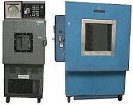
Fig.
1. Examples of
Temperature
Cycle Machines |
Electrical
testing
of the samples to device specifications shall also be performed to
detect electrical
failures accelerated by the temp cycle.
Failure
acceleration due to Temp Cycling and
Thermal Shock depends on the following
factors: 1) the difference between the high and low temperatures
used; 2) the transfer time between the two temperatures; and 3) the
dwell times at the extreme temperatures.
Failure mechanisms
accelerated by temperature cycling include die
cracking, package cracking, neck/heel/wire breaks, and bond lifting.
For reliability testing or
qualification of new devices, 1000 temp cycles are usually performed,
with interim visual inspection and electrical test read points at 200X
and 500X.
Two industry standards that
govern Temp Cycle Testing are the Mil-Std-883 Method 1010 and the JEDEC
JESD22-A104.
Mil-Std-883, Method 1010 Specs :
Temperature Cycle Test
-
Total Transfer Time <= 1 minute
-
Total Dwell Time >= 10 minutes
-
Specified Temp reached in <= 15 minutes
- Must be conducted for a minimum of 10 cycles
Table 1. Mil-Std-883
Method 1010 Temp Cycle Test Conditions
|
Condition |
Low
Temp |
High
Temp |
|
A |
-55
(+0/-10) deg C |
85 (+10,-0)
deg C |
|
B |
-55 (+0/-10)
deg C |
125 (+15,-0)
deg C
|
|
C |
-65
(+0/-10) deg C |
150 (+15,-0)
deg C
|
|
D |
-65
(+0/-10) deg C |
200 (+15,-0)
deg C
|
|
E |
-65 (+0/-10)
deg C |
300 (+15,-0)
deg C |
|
F |
-65 (+0/-10)
deg C |
175 (+15,-0)
deg C |
JEDEC
JESD22-A104 Specs :
Temperature
Cycle Test
-
Total Transfer Time <= 1 minute
-
Total Dwell Time >= 10 minutes
-
Specified Temp reached in <= 15 minutes
-
Recommended for lot acceptance screen : 10 cycles
-
Recommended for qualification :
1000 cycles
Table 2.
JEDEC JESD22-A104 Specs
Temp
Cycle Test Conditions
|
Condition |
Low
Temp |
High
Temp |
|
A |
-55
(+0/-10) deg C |
85 (+10,-0)
deg C |
|
B |
-55 (+0/-10)
deg C |
125 (+10,-0)
deg C
|
|
C |
-65
(+0/-10) deg C |
150 (+10,-0)
deg C
|
|
D |
-65
(+0/-10) deg C |
200 (+10,-0)
deg C
|
|
F |
-65 (+0/-10)
deg C |
175 (+10,-0)
deg C |
|
G |
-40 (+0/-10)
deg C |
125
(+10,-0) deg C |
|
H |
-55 (+0/-10)
deg C |
150
(+10,-0) deg C |
Reliability
Tests:
Autoclave
Test or PCT; Temperature
Cycling; Thermal
Shock;
THB;
HAST;
HTOL;
LTOL;
HTS; Solder
Heat Resistance Test (SHRT);
Other
Reliability Tests
See Also:
Reliability
Engineering;
Reliability Modeling; Qualification
Process; Failure
Analysis;
Package Failures; Die
Failures
HOME
Copyright
©
2001-Present
www.EESemi.com.
All Rights Reserved.

